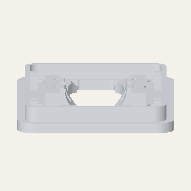
Cradle
ASA
An external G3 Flex camera enclosure with an interior support, TPU gaskets and a recessed network socket for mounting on a kennel wall.
These non-printed parts are needed to complete the project.
| Quantity | Part | Use in construction |
|---|---|---|
| 1 | UniFi G3 Flex camera | Camera retained by the cradle and clamp |
| 4 | M5 through bolts, length to suit the seated stack | Fasten the enclosure and interior support through the kennel wall |
| 4 | M5 nuts | Secure the four wall fasteners |
| 8 | M5 flat washers, sized to fit the 12.4 mm interior recesses | Spread wall-fastener loads and bridge the sleeve openings |
| 4 | Metal compression sleeves, 8 mm OD with clearance for M5 bolts | Limit compression across the wall, gaskets and mounting plates; cut to the measured bearing span |
| 4 | M4 clamp bolts, length to suit the assembled clamp | Secure the camera clamp to the cradle |
| 4 | M4 cover bolts, length to suit the cover attachment | Secure the removable cover to the cradle |
| 8 | M4 nuts, approximately 7 mm across flats and at most 5 mm tall | Fit the captive nut pockets for the clamp and cover |
| 8 | M4 flat washers, no more than 9 mm OD | Provide bearing surfaces for the clamp and cover fasteners |
| 1 | VCE Cat6 RJ45 female-to-female keystone coupler (ASIN B075ZPGV1H) | Provide the recessed external network socket |
| 1 | Short flexible Cat6 patch lead, approximately 150 mm | Connect the keystone coupler to the camera inside the cover |
ASA
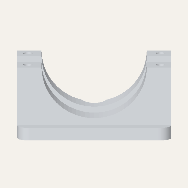
ASA
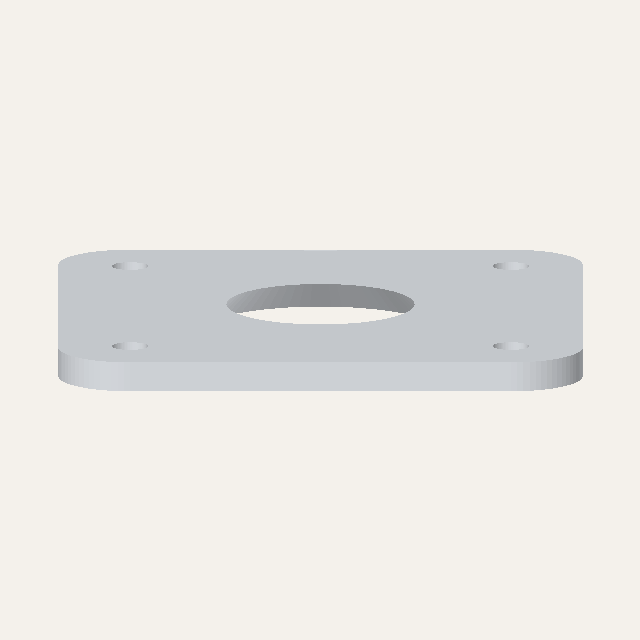
ASA; TOP dash on the flat gasket-facing side
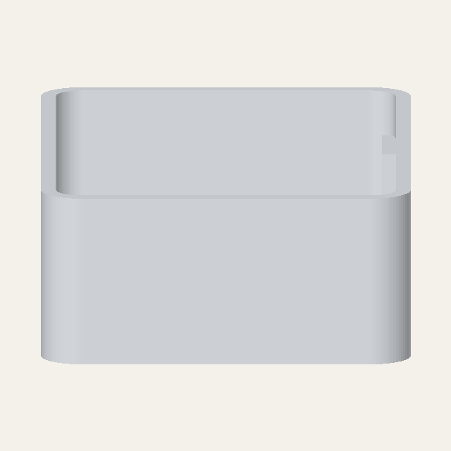
ASA
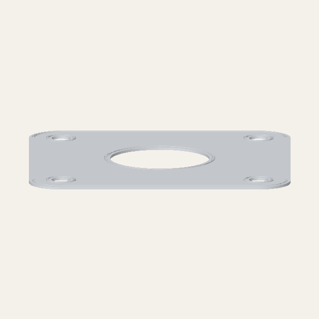
TPU 95A HF
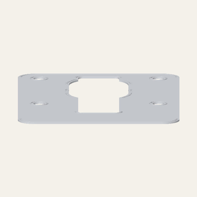
TPU 95A HF
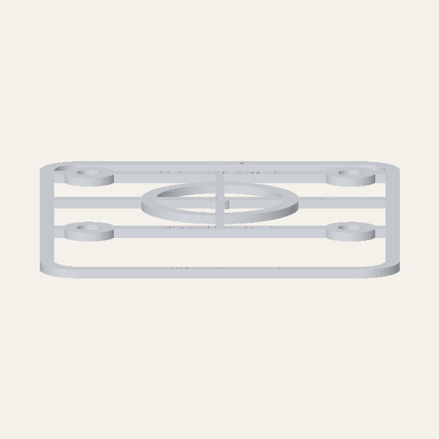
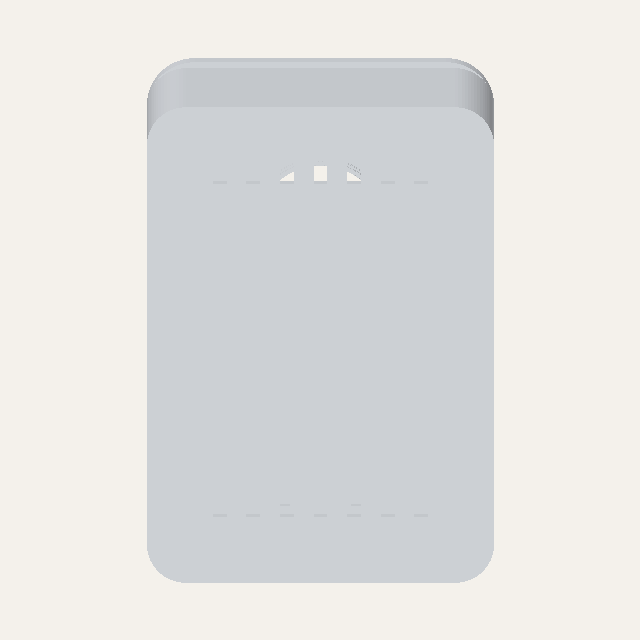
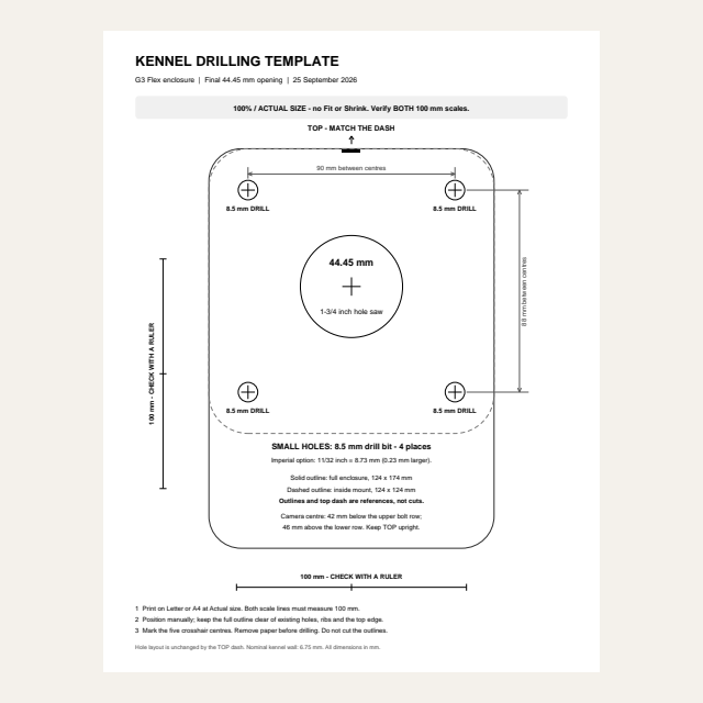
Manual alignment tool; check dimensions before marking the kennel
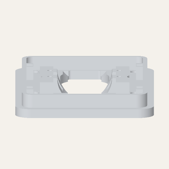
P1S, 0.4 mm nozzle; ASA on Textured PEI. Slice after opening.
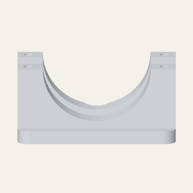
P1S, 0.4 mm nozzle; ASA on Textured PEI. Slice after opening.
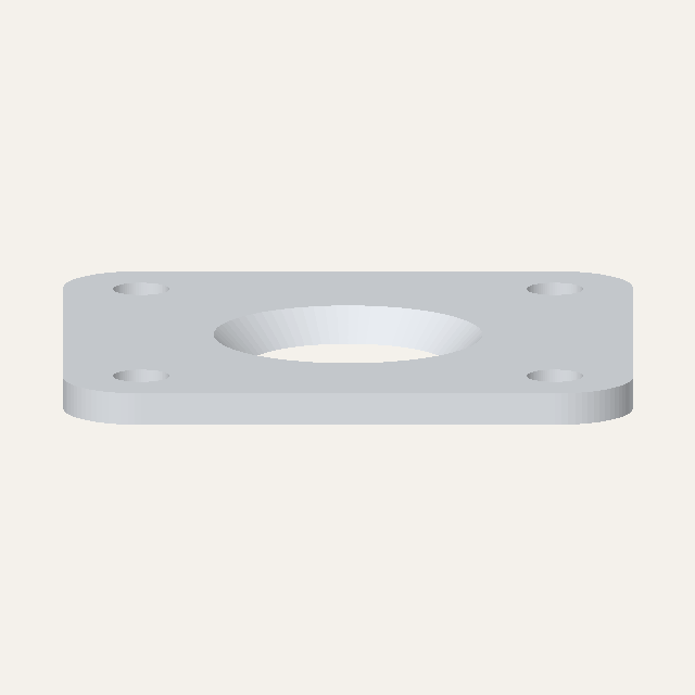
P1S, 0.4 mm nozzle; ASA on Textured PEI. Slice after opening.
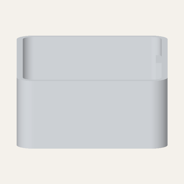
P1S, 0.4 mm nozzle; ASA on Textured PEI. Slice after opening.
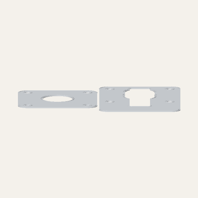
P1S, 0.4 mm nozzle; TPU 95A HF from the external spool on Smooth PEI.
Six installed parts with a transparent cover; gaskets shown at nominal installed thickness. Viewing model, not a print layout.
The camera sits outside the kennel, with its lens looking through a circular opening in the wall. A cradle and separate clamp hold the G3 Flex body parallel to the wall; aiming uses the camera's own adjustable head. An interior support spreads the mounting load, and a removable cover surrounds the camera and cable connection.
The cover includes ventilation slots, a closed bottom and a recessed side port for a Cat6 keystone coupler. A short patch lead connects the coupler to the camera, leaving a socket on the outside of the enclosure for the PoE cable. The viewing opening and ventilation remain open; this is not a sealed waterproof housing.
Print one cradle, clamp, internal fixture mount and cover in ASA. The two separate gaskets use TPU 95A HF. The reusable printed drilling template is an additional installation tool. The small recessed dash on the internal mount marks the top of its flat, gasket-facing side.
The downloads contain seven individual STLs, a full-size paper drilling template, five Bambu Studio print projects and an assembled viewing model. Import STLs in millimetres at 100% scale. The assembled model is for inspection; use the individual parts or print projects for printing. Its gaskets are shown at their nominal installed thickness, while the printable gasket files retain their full height.
| Dimension | Nominal value |
|---|---|
| Enclosure footprint | 124 x 174 mm |
| Projection from outside of kennel wall | 66.4 mm |
| Internal support | 124 x 124 x 7 mm |
| Kennel wall used for the mounting stack | 6.75 mm |
| Camera opening | 44.45 mm / 1-3/4 inch |
| Four mounting holes | 8.5 mm, on a 90 x 88 mm pattern |
| Gaskets | 1.6 mm free height; nominally 1.5 mm each installed |
Print the paper template on Letter or A4 at 100% / Actual size, with Fit and Shrink disabled. Check that both calibration lines measure 100 mm before using it. The template labels every smaller hole for an 8.5 mm drill bit. An 11/32 inch bit is 8.73 mm, which makes a slightly larger hole. The camera opening uses a 1-3/4 inch hole saw.
Place the template manually below the kennel's existing holes, keeping the full enclosure outline clear of holes, ribs and the top edge. It does not register into the existing holes. Mark the five crosshair centres, then remove the template before drilling. The camera opening is 42 mm below the upper mounting row and 46 mm above the lower row. No locating collar enters that opening.
Use four M5 through bolts with metal compression sleeves and washers for the wall attachment. The nominal sleeve bearing span is 20.65 mm with the specified wall and installed gaskets; measure the actual seated stack before cutting. The interior washer recesses are 12.4 mm wide. Washers must bridge the sleeve openings and sit flat in the recesses. Four M4 fasteners secure the camera clamp and four secure the cover. Select bolt lengths to suit the seated stack and nut engagement.
Set the camera aim before fitting the cover. Fit the VCE Cat6 keystone coupler with its spring clip toward the installed top, and connect the short internal patch lead. Check the cable clearance, hardware seating and complete day/night camera view before putting the kennel into service.
The Bambu Studio projects use a P1S with a standard-flow 0.4 mm nozzle. Select the actual filament source and matching physical plate before printing.
| Files | Material and plate | Key settings |
|---|---|---|
| Four enclosure print projects | ASA; Textured PEI | 0.20 mm layers, 4 walls, 25% gyroid, 270 C nozzle / 100 C bed, 8 mm outer brim |
| Combined gasket print project | TPU 95A HF; Smooth PEI | 0.20 mm layers, solid gaskets, 230 C nozzle / 35 C bed, external spool |
The internal mount is oriented with its marked flat face on the bed and washer recesses upward. TPU 95A HF feeds from the external spool on this P1S setup. The printed drilling template is supplied as an STL without a prepared print profile.